Process simulation is used to understand why a defect or problem occurs during the manufacturing process. In an ideal world, the design process would not allow these problems to ever hit the shop floor. Leading companies, such as JLO Metal Products in Chicago, Illinois have used DEFORM™ to analyze aluminum impact extrusions at the quotation stage.
Read More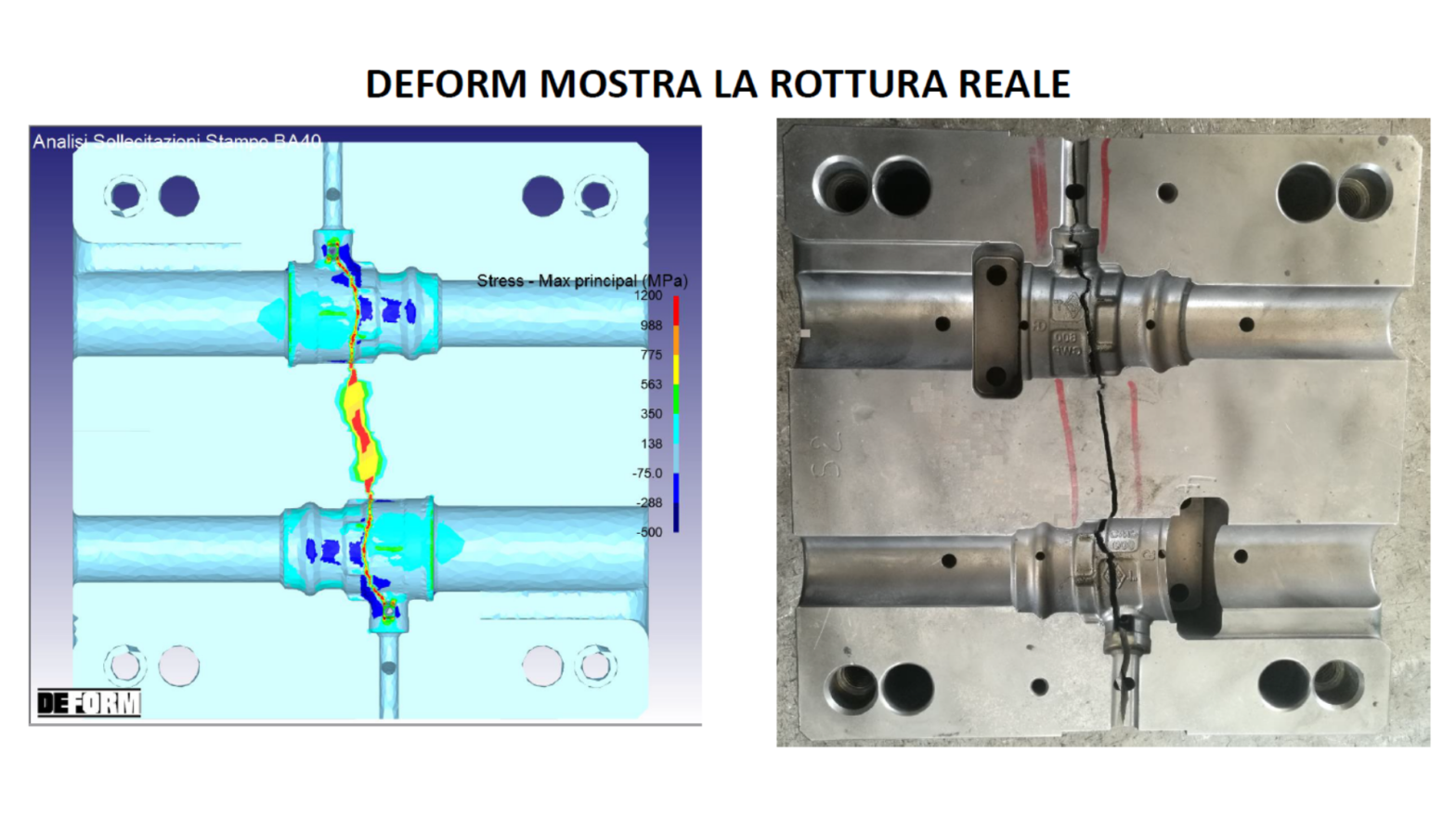
1. The DEFORM hot forming simulation software showed the problem on the die. Excellent alignment of “Simulation Software Results” with “Reality” 2. The simulation allows to identify the defects obtained during forming, to understand their causes and then to take the right corrective actions. Positive sampling at the first shot, if simulated 3. Reliable raw material supply 4. Start-up times reduced to a minimum: bar and positioning already defined 5. Machine definition required: sampling and production planning 6. Increased die life thanks to positive samples that do not require subsequent modifications and repairs, even with possible welding 7. Estimate Reliability Verification 8. Shorter cycle time (Article in Italian)
Read More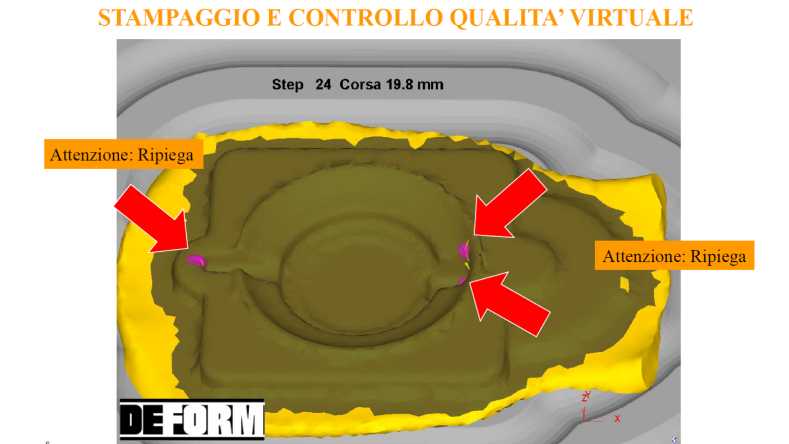
1. The DEFORM hot forming simulation software showed the problem on the part. Excellent alignment of “Simulation Software Results” with “Reality” 2. The simulation made it possible to identify the defects obtained during forming, to understand their causes and then to take the right corrective actions. Positive sampling at the first shot, if simulated 3. Reliable raw material supply 4. Start-up times reduced to a minimum: bar and positioning already defined 5. Machine definition required: sampling and production planning 6. Increased die life thanks to positive samples that do not require subsequent modifications and repairs, even with possible welding 7. Estimate Reliability Verification 8. Less cycle time ....
Read More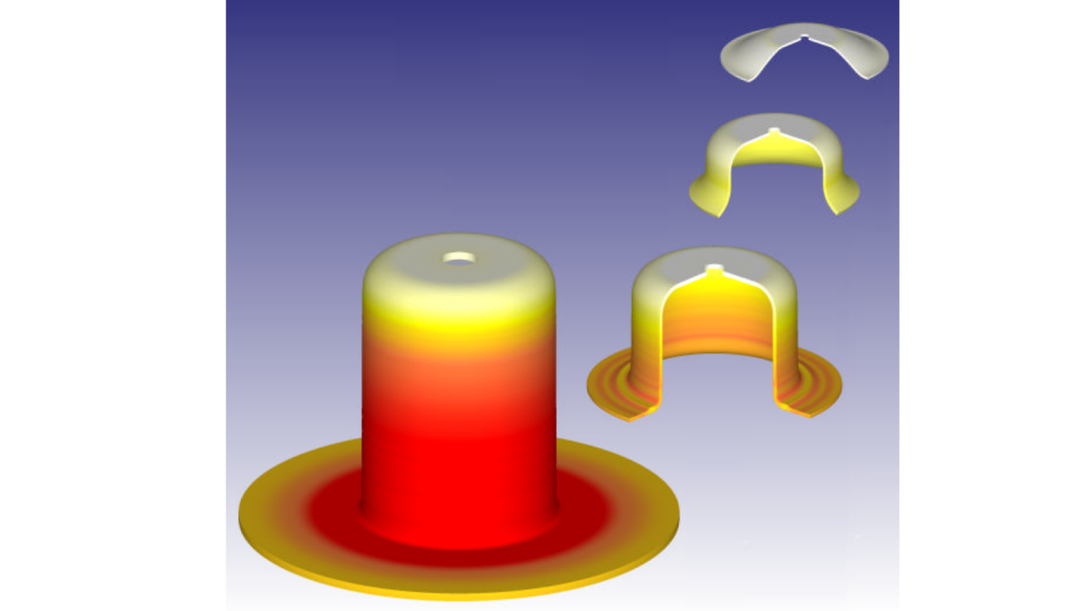
Using DEFORM™, the OSU/ERC team was able to design a progressive die sequence to make the cupped part in 10 stations. While an extra station was required in this example, the methodology was shown to be sound.
Using this methodology with experienced designers should result in fewer operations. Figure 4 shows the comparison between the emperical design and the design conducted using FEM. It can be noted that the FEM designed progression exhibits reductions that are more consistent from one station to the next. More aggressive wall thinning limits in the early stations could have been used.
This example illustrates how DEFORM™ is capable of optimizing a progressive die sequence.
This paper addresses two issues in the 3-D numerical simulation of sheet metal forming processes. One is the implementation of an effective solid element on very thin metal sheet under the bending and drawing operations. The other is the use of parallel computational scheme to reduce the simulation time. Possible volumetric and shear locking phenomena for the thin structure with solid element are avoided by adopting the assumed strain concept.
Read More
The case study was supplied by Nicro SpA of Vailate, Italy. It was performed in partnership with the University of Brescia and ECOTRE Valente Srl of Brescia, Italy.
ECOTRE is the exclusive distributor of the DEFORM system in Italy.
SFTC and ECOTRE would like to thank Mr. Marena Gianni for sharing this DEFORM experience.
Magnesium alloys can provide great
weight reductions in components,
which would otherwise be made from
steel or polymeric materials. Those
used in current structural parts tend
to be die-castings, which are prone
to porosity and are usually quite
bulky in nature.
After 3 seconds of heating the blank
in the tooling, DEFORM™ predicted
the temperature distribution prior to
forming ...
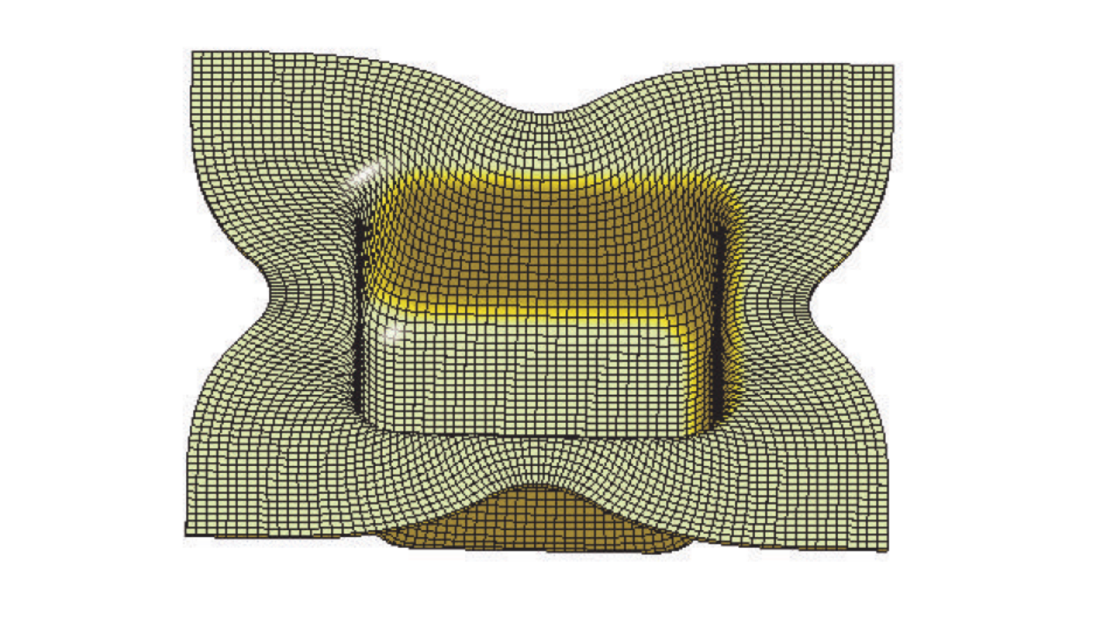
The industrial drawing of automotive shock absorber endcaps caused wear and radial brittle fractures of the tool steel dies. A finite element method (FEM) simulation of the process showed that this was caused by high contact and hoop stresses on the die. Such difficulties are usually solved by expensive changes in the die material, but a change in the punch design was proposed as a simpler and cheaper solution. The new punch geometries were employed in a FEM simulation of the drawing, indicating much lower contact and hoop stresses. The implementation of the solution eliminated the wear and brittle fracture problems.
Read More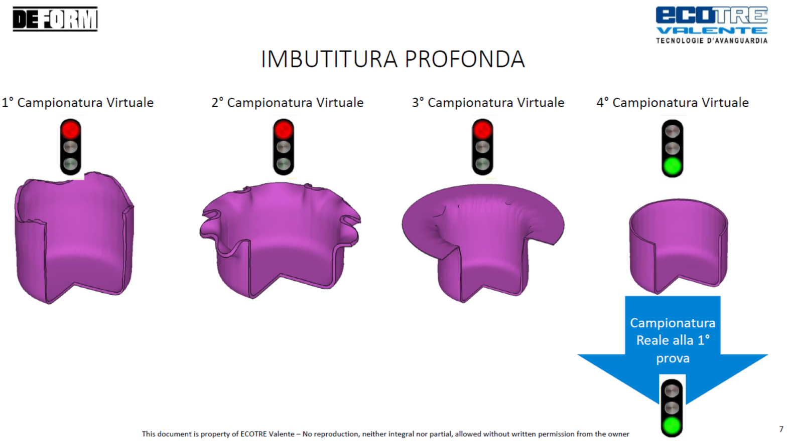
1. The DEFORM software of simulation metal sheet forming, deep drawing, progressive forming, blanking and heat treatment showed the problems on the part. Excellent alignment of “Simulation Software Results” with “Reality” 2. The simulation allows to identify the defects obtained during forming and shearing, to understand the causes and then to take the right corrective actions. Positive sampling at the first shot, if simulated 3. Reliable raw material supply 4. Start-up times reduced to a minimum: coils, strips, sheets already defined 5. Machine definition required: sampling and production planning 6. Increased die life thanks to positive samples that do not require subsequent modifications and repairs, even with any welding. Wear, elastic deformations of the die, cracks identified by DEFORM 7. Estimate Reliability Verification 8. Shorter cycle time Article in Italian
Read More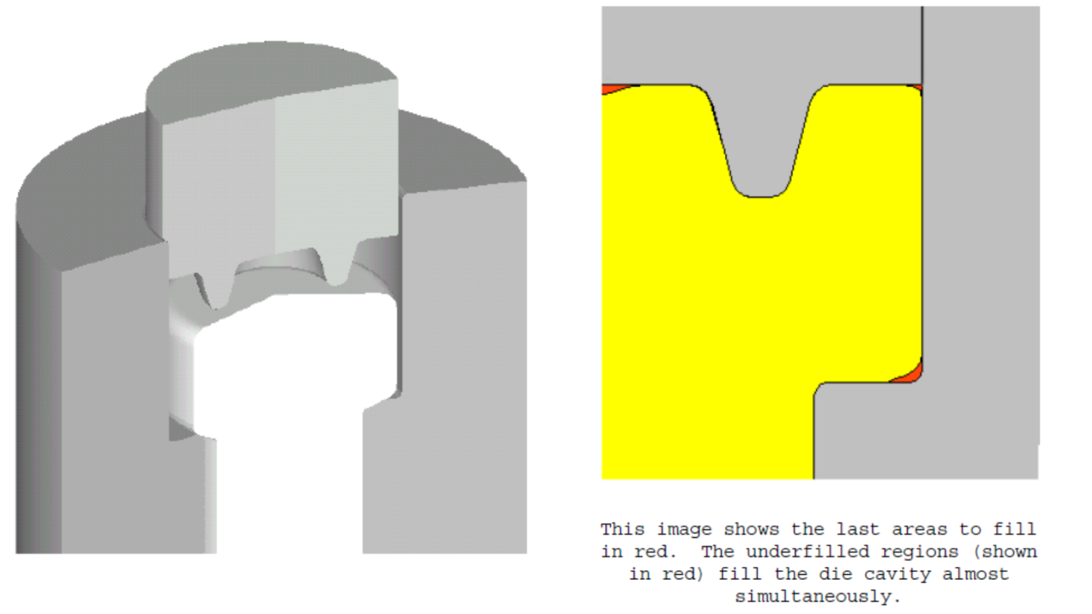
The final design was one of a number of options simulated using DEFORMTM. The preform shape was adjusted until all critical corners were filling the die cavity at the same time during the die stroke. This optimum preform design resulted in a load that was significantly lower than the original design and the two intermediate improvements.
The final load was 515 tons, or a 22% improvement over the first preform design. It is clear that this process will be more robust and experience longer die life.
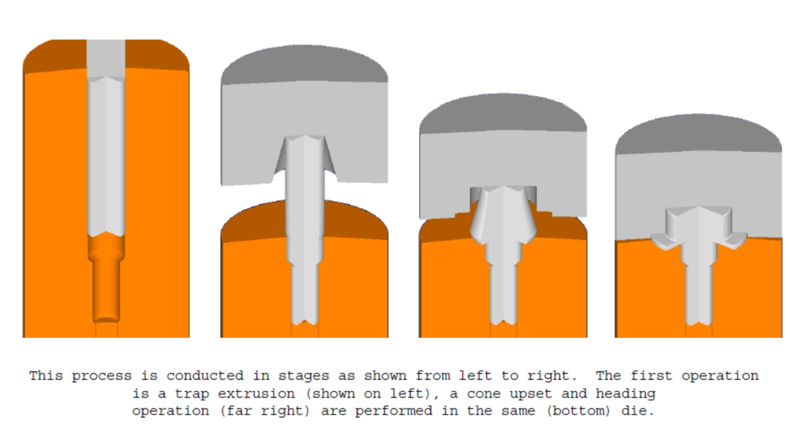
Bolt Progression
A study was conducted on the manufacture of a flanged shoulder bolt blank on a two die – three blow header. The method of manufacture is a common one that includes trap extrusion of the initial wire, a cone upset and final forming of the head without the use of sliding dies.
In this case, the wire diameter was varried from .325” diameter thru .425” diameter, with the subsequent processes adjusted to accommodate this variation.
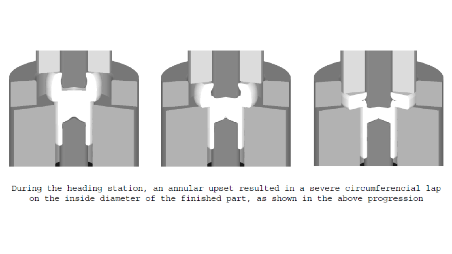
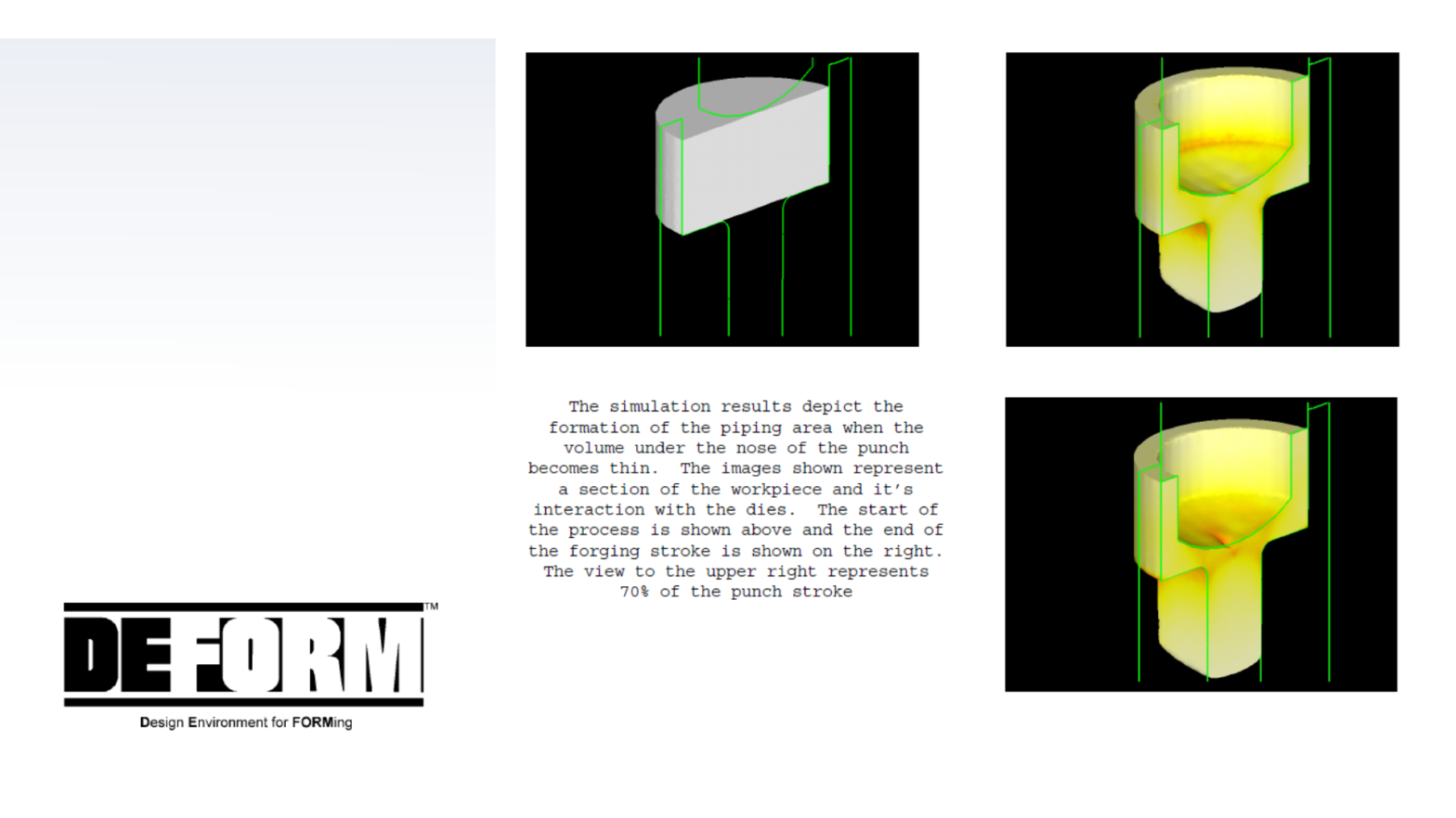
During the development of a heading progression, the designer typically balances many complex parameters to accomplish a workable process. These parameters include the number of intended operations, required volumetric displacements, final part geometry, starting material size, available forming equipment and the behavior of the workpiece. Frequently, variations have existed between the designer’s concept of the progression and the actual shop trial. When unexpected metal flow occurs, this can result in a part with unfill, excessive loads, die breakage, laps, ductile fracture or other production problems. All of these problems are very costly.
Read More